
A repeat sheet-metal part requires tooling suited to the product and process. TOS manages sheet metal tooling from China for stamping, punching, deep drawing and progressive dies. Your drawing, material and expected volume form the basis for tool selection.
We coordinate the operation sequence, press interface and sample assessment. Corrections, wear parts and ownership are also included in the enquiry. You retain one Dutch point of contact for technical coordination and transfer into series production.
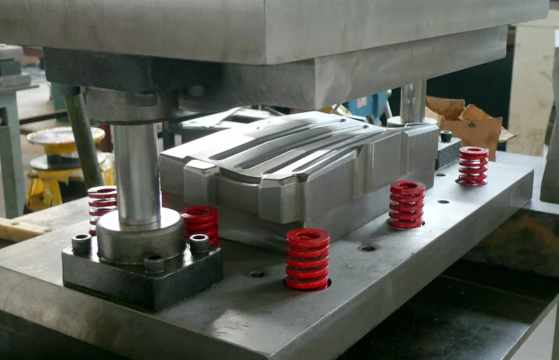

Stamping, punching, deep drawing or a progressive die.

Assess material, operations and machine connection together.

Measure and assess against defined requirements.

Record ownership, maintenance, wear parts and documentation.
Technical coordination from request to production.
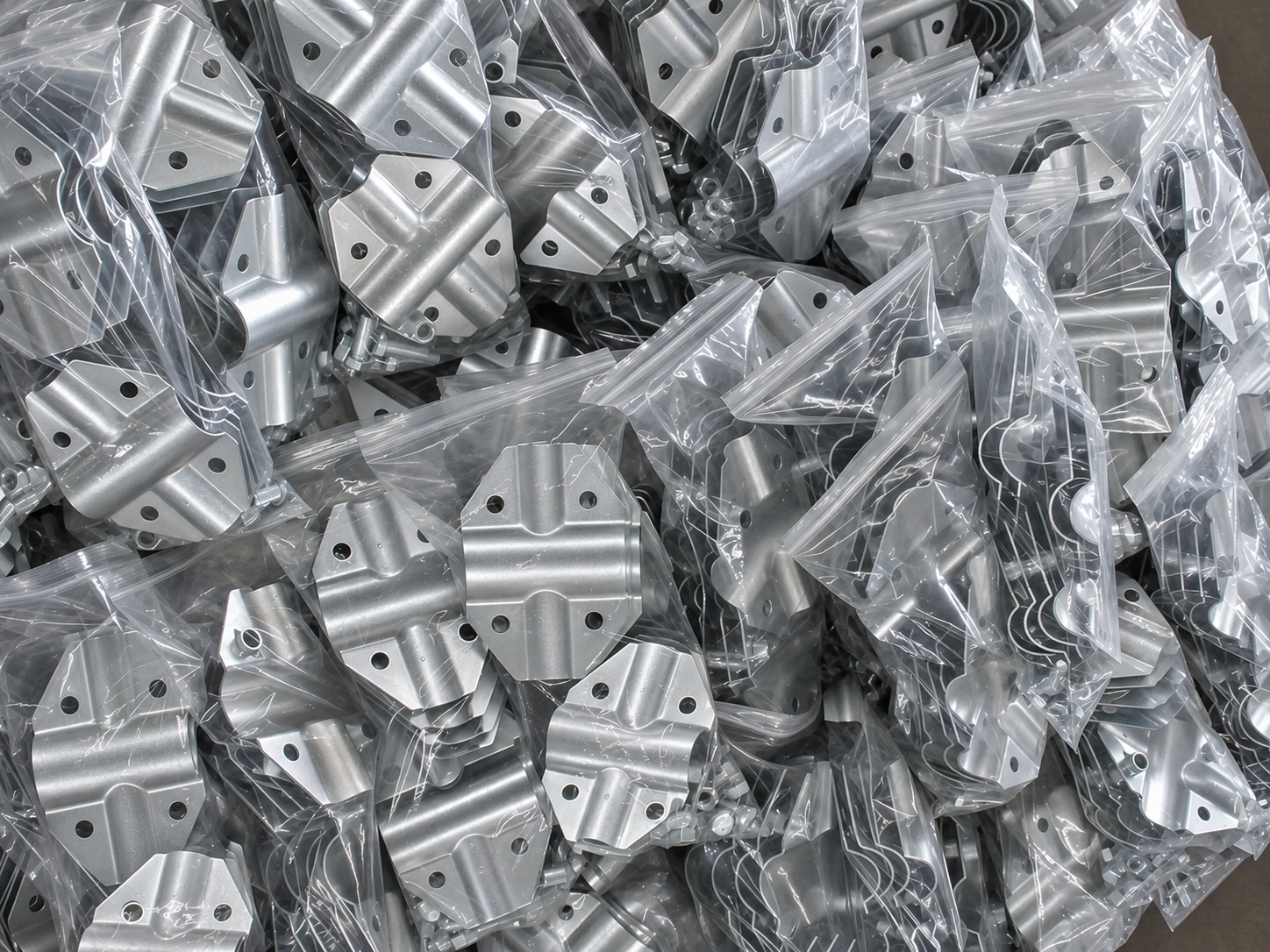
The function of the part determines which operations are required. A flat mounting plate with holes requires different tools than a deep cap or a curved clip. Therefore, name the final contour, holes, deformations and connection dimensions. TOS assesses the tool as part of the complete production route.
When cutting out an outer contour, the cut part is the desired product. For example, punching creates holes and recesses in the material that is retained. One product-related tool can combine multiple cutting operations. The toolmaker tailors punches, cutting plates, guidance and removal of cutting waste to the part.
Determine the permitted burr, burr direction and requirements for the cutting edge. These partly determine whether deburring or another follow-up operation is necessary. Before the parts are delivered, also read about die cutting and punching in China.
For hollow shapes, we supervise the coordination of stamp, die and, where necessary, fold holder. Material feed, radii and draw depth are reviewed together. Depending on the shape, several pulling steps and subsequent trimming or calibration may be required. The desired final shape therefore does not yet prove that the part can be made in one drawing step.
The tool request is in line with the agreements for deep drawing parts from China, such as minimum wall thickness in designated places, fit and visual quality.
With a progressive die, also called a follow-up die, metal strip is fed step by step through successive stations. Those stations can combine punching, cutting and forming. The part typically remains connected to a carrier strip during operations and is released at the end.
The strip layout is an important design decision. Bandwidth, feed step, positioning, and the order of cutting and forming must match. Material use, waste disposal and accessibility for maintenance also count. An additional station may be technically necessary; the smallest tool is not automatically the best solution.
This approach can suit stable products with recurring purchases and multiple operations. Compare the investment with a route via separate tools or laser cutting in preparation for further sheet metal processing. A prototype that can be easily made with a laser and a bending machine does not confirm that a progressive tool is economically suitable.
Discuss changes in holes, lips or bending directions before tool construction. TOS links possible product optimization to the function of the part, so that a proposed adjustment can first be reviewed substantively.
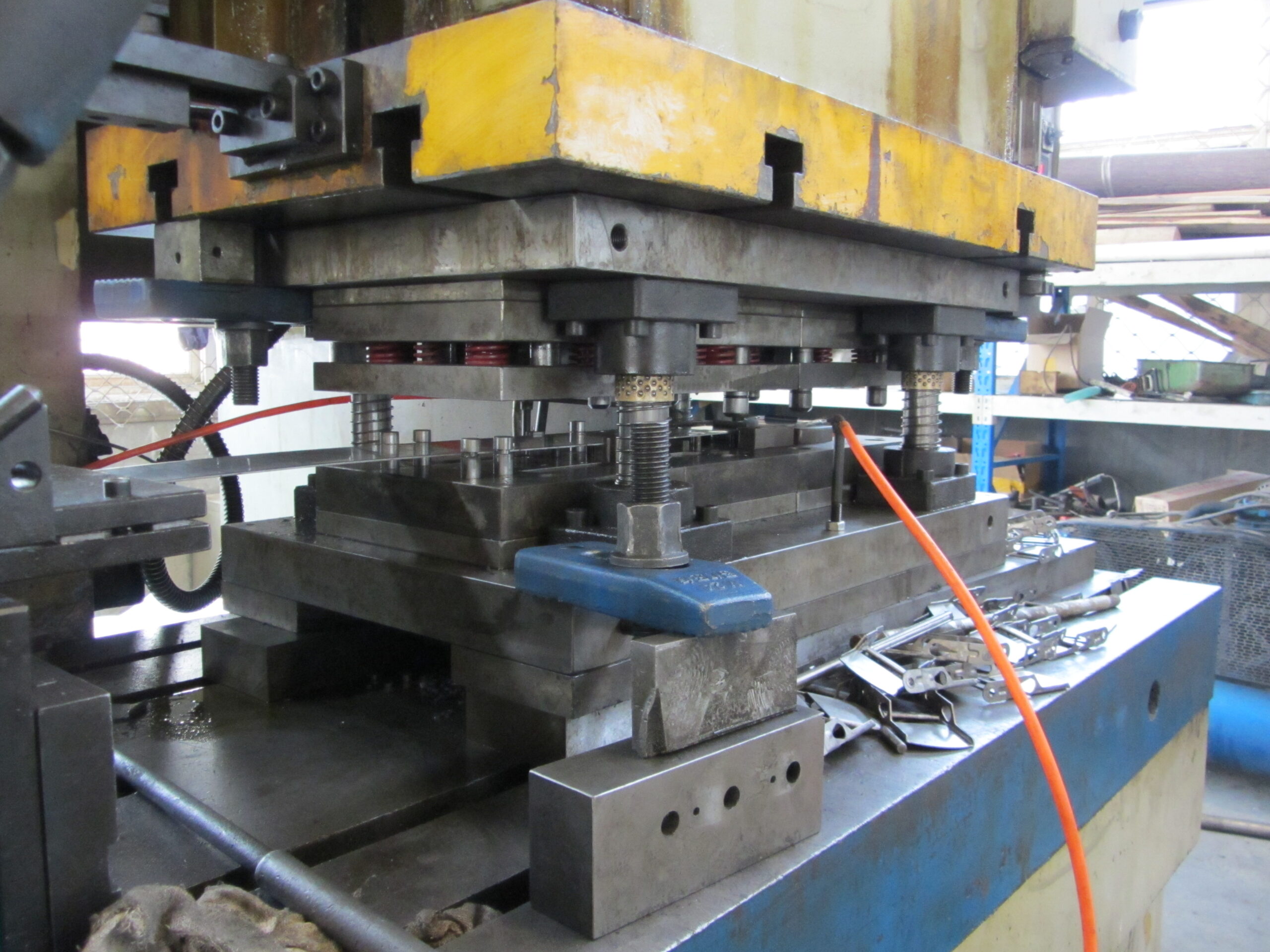

Collect drawing, sheet quality, thickness and volume.

Review operations, strip layout or draw steps.

Create tools for the agreed production environment.

Measure test products and reassess corrections.

Arrange documentation, maintenance and possible transfer.
Specify the exact sheet quality and starting thickness. Material strength, delivery condition, thickness variation and any coating influence the choice of tools. Deformability also plays a role in deep drawing. A material change after making the tool may require a new assessment or adjustment.
For stamping and punching, the cutting clearance between punch and tool is chosen based on the material and product requirements. This choice influences, among other things, the cutting edge and load of the tool. There is no universal clearance or accuracy for every sheet metal part. Record critical dimensions, permitted edge deformation and the desired finish on the drawing.
With deep drawing tools, risks such as folds, cracks and local thinning are reviewed. At bending and forming stations, springback also counts. Agree whether a shape analysis or simulation is part of the preparation and which test products are needed afterwards.
A tool must match the intended press and input. The production partner assesses, for example, force requirements, stroke, assembly height, tool dimensions, mounting and material supply. A progressive tool also includes belt feeding and monitoring. Are the tools requested for use on your own press? Then provide the machine data immediately.
Create a inspection plan for the trial production. Link a measurement report to the correct drawing revision and measurement references. Where necessary, also assess flatness, bend angles, fit, burrs and visible surfaces. A dimensional check of a flat test piece does not replace a check of the final formed product.
A tool can only be used if it produces the right parts in the agreed production environment. Therefore, record how test products are reviewed and who issues the release. For a progressive tool, the coherence between the stations is part of that assessment; for a deep drawing tool also the agreed drawing sequence.
Compare quotes on the same scale. Design, tool construction, test material, test production, measuring work and correction rounds may be included differently. Distinguish between a tool correction and a later change to your product. Also discuss any separate trimming, bending or calibration tools and further finishing.
Agree on identification, ownership, storage, maintenance and replacement of wear parts. Record which drawings, parts lists, setting data and spare parts are supplied. A fixed service life or guaranteed number of strokes cannot be assumed without information about material, design and use.
When transferring to another location, tools, press and peripheral equipment must be readjusted. Packaging, corrosion protection and a possible new test run are also part of the preparation. Mere ownership of the tool does not make it suitable for every press.
Continue to work with the released revision and inspection agreements for repeat orders. TOS connects the tooling process with quality inspection and the complete guidance of outsourcing production to China.
Share the final drawing, revision, 3D files where available, application and expected orders. Indicate critical dimensions, visible surfaces and the desired delivery condition of the part.
Record sheet quality, thickness and delivery condition. Check which cutting edges, holes, bends or drawn shapes are required and which requirements only apply after subsequent processing.
Compare separate punching or punching tools, a deep drawing route and a progressive die where relevant. The concept must match product complexity, volume and change risk.
Assess the strip layout or pulling sequence and the technical connection to the press. Coordinate material supply, positioning, removal and necessary follow-up operations.
Record design scope, sample products, corrections, acceptance criteria and schedule. Also make agreements about ownership, documentation, maintenance and any transfer of tools.
The toolmaker builds and assembles the released concept. Agree which design data and progress information will be shared during this process.
Make test products with the agreed material and the intended production route. Assess sizing and product function and check relevant cutting and shape characteristics.
Record deviations and determine whether adjustments to tools, settings or product design are necessary. Review new trial products before release.
Save the agreed drawings, measurement results, setting data and reference parts. Coordinate wear parts, maintenance, storage and the procedure in case of damage.
Start series production according to the released agreements. When the tool is delivered to another location, machine connection, transport protection and a new test run are coordinated in advance.
When cutting out an outer contour, the cut out part is the desired product. For example, punching involves making holes or recesses in the material that is retained. These operations can be combined in a product-related tool. The specific functions are central to the tool request.
A progressive die can fit recurring runs of a stable part with multiple cutting and forming operations. The strip layout, use of materials, investment and available press partly determine the choice. There is no general minimum quantity that applies to each product.
This is possible after assessing the material, product shape and tool concept. Deep drawing can require several steps. For some parts, drawing operations can be included in a follow-up tool; for others, a separate tool route is a better fit. This will be coordinated before construction.
This must be reviewed in advance based on your press, input and other peripheral equipment. Share machine data, mounting options and the intended production route, among other things. Also agree on documentation, trial run and acceptance at the receiving location.
Shape complexity, material, number of operations, stations and tool structure determine the investment. Trial production, measurement work, corrections, spare parts and transfer data also count. Therefore, compare the complete assignment and the expected product delivery.
Technical request
Upload a PDF, DWG or STEP/STP file and receive a detailed response about manufacturability, the production route and your request for quotation.